Project: Electronic Steering Wheel
Hello everyone!
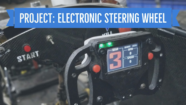
In the blogpost below, I share one of my favourite projects, and that is the electronic steering wheel. I designed and developed the steering wheel for a formula student car. The function of the electronics on the wheel are to basically control several systems of the car like settings for radiator fan, drag reduction system and variable length intake manifold. To get a brief idea, first watch the video below and then continue with the post.
The Setup
The setup can be divided into 4 levels of hierarchy. Consider the diagram below:
- Arduino:The role of arduino in my setup is to receive input from the touch screen and gear shift buttons and accordingly deliver an output signal to control all the relays and servo.
- Steering wheel and actuators:
- Quick release electrical coupling: As far as the production of the steering wheel is concerned, this was undoubtedly the most difficult part of the entire setup. The male side of a round electrical connector was inserted in the splined shaft of the steering wheel with all the wiring going through the shaft and exiting near the rack. The female side of the electrical connector was positioned inside the quick release coupling of the steering wheel. A total of 8 wires are carried by the connector. Check the images below to get a better idea of the connections.
- Pneumatic gear shifter relay: The relay is controlled by the arduino which receives the signal from gear shift buttons on the steering wheel. When the button is pressed, the relay is activated by the arduino and the pneumatic system moves accordingly to change the gear.
- DRS Servo: The servo for the DRS(Drag reduction system) is also controlled by the arduino. According to the event selected by the user in the "Event Selection" menu on LCD, the servo moves and the position of the rear wing of the car is changed.
- VLIM Servo: VLIM stands for variable length intake manifold.Just like the DRS servo, the VLIM servo is controlled by the arduino according to the settings in the event selection menu.
- Radiator fan relay: The radiator fan is a critical part of the engine's cooling system. Don't turn the radiator fan on and the engine overheats. Keep the radiator fan always on and you drain your battery within 15 minutes. Hence, there are many settings that the user can select depending upon the ambient air temperature and running conditions.
- Steering wheel electrical circuit: As the name suggests, it is the electrical circuit of the steering wheel. A total of 8 wires from the electrical circuit go to the quick release electrical coupling.
- Steering wheel auxiliaries
- Shift Lights: These are the LED lights mounted on the top of the steering wheel. They are used to inform the driver to shift the gear at optimum RPM in order to extract maximum performance from the powertrain. In my setup, we used Neopixel WS2812B RGB LED's for the reasons of simplicity. The entire strip is operated by only 3 wire. One power(+5v), second ground and the third is the signal wire.
- Touch Screen: As discussed above, the touch screen is operated by the driver to control various settings of the car. The touch screen device that we used is a Nextion device. The device offers an easy way to interface with the arduino and beautiful GUI's can be made with ease without much programming skills. To explain the coding and design of the touch screen would need a tutorial of it's own. Let me know in the comments section below if you want me to make a tutorial for the same.
- Shift Buttons: Here again, when the buttons(either of two) are pressed by the driver, the respective digital read pins of the arduino are set to high. According to the button pressed, arduino activates the appropriate pneumatic gear shifter relay and the gear is changed.
Production
Apart from the quick release electrical connector assembly which i've already discussed above , the main components of production are the base frame and the cover boxes. The base frame of steering, as visible in the images, was made using carbon fibre. Three layers of carbon fibre on either side of a foam core were bagged using resin infusion technique. After drying all the epoxy, the part was sent for wire cut where the slots for thumb and the external profile were cut on the base frame. As for the cover boxes, 2mm PVC sheets were used, which were then again sent for wire cut to get the desired profile. After the machining, both the base frame and the cover boxes were assembled using nuts, bolts and a lot of epoxy. :P
Below is another video made during the time of manufacturing. Making car sounds is always fun.:)
Hope you enjoyed the project. If you have any suggestions/complaints or questions feel free to comment below. :)


Thank you for this fantastic post; it has helped me understand quick release coupling manufacturer in India Mumbai.
ReplyDeleteNice articles and your information valuable and good articles thank for the sharing information Air manifold fabrication
ReplyDeleteGet full details about the Advanced Diploma in Automotive Mechatronics (ADAM) — from eligibility and fee structure to career pathways in the evolving auto-tech sector in 2026. To read the full blog Click here Thank You.
ReplyDeleteNot sure which branch to pursue? Compare ADAM and Mechanical Engineering in terms of future scope and opportunities. To read the full blog Click here Thank You.
ReplyDelete